Well I can honestly say this is one of the more challenging projects I have faced recently, the complications of every PSU having different settings and wires etc can be a nightmare but I did however manage to make this work after a little tinkering.
OBJECTIVE
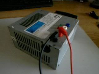
To convert a standard 300 Watt Seasonic PSU Model: SR-300FS to a lab power supply with multiple voltage outputs.
/!\ WARNING: This is VERY dangerous as you are dealing with 240v AC power which can kill you instantly. Only experienced and qualified professionals should attempt this. I am in no way responsible for your action and this guide is only here as reference. Please use extreme caution if attempting to duplicate what I have done here. /!\
COMPONENTS
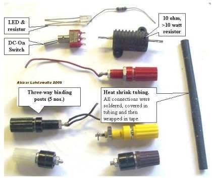
- 300 Watt PSU (Can be more but wouldn't recommend it)
- 2x 5mm LEDs (I used one red, one green)
- A SPST Switch
- 5 or 6 4mm Sockets
- 10Ω 10W Resistor
- Heat shrink tubing
- Electronic tape
- Connector block
- 2x 330Ω Resistors
STEP ONE
Unplug any power cord from the PSU and remove it from the PC Case if still attached (normally only about 4 screws hold it in place).
Cut off the connectors but leave a about 3 or 4 inches on them as you can use them later on for other projects.
You need to discharge the PSUs capacitors as these can still carry a lethal current for many days after you unplug the PSU form the mains. You can do this by either leaving it for a week to discharge or connect the 10Ω 10W resistor across a black and red wire; this will take seconds to discharge it.
Gather the components you need together.
STEP TWO
Open up the PSU, again normally only about 4 screws holding the cover down.
Now you need to start bundling the wires together to make your life easier.
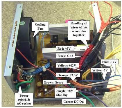
Here are the colour codes for the wires:
- RED = +5v
- BLACK = Ground (0v)
- WHITE = -5v
- YELLOW = +12v
- BLUE = -12v
- ORANGE = +3.3v
- PURPLE = +5v (Standby Cable)
- GRAY = Power on to PSU
- GREEN = Power on switch to DC Rails
STEP THREE
Now this next step really depends on your make and model of PSU.
You need to start drilling your holes for your Sockets, LEDs and Switch. Now be careful whilst doing this as you don't want to get metal filings in the circuit board so if you are drilling in the side of the unit make sure you removed the PCB first. If you are drilling in the lid then don't worry. Here are two examples of how to do it:
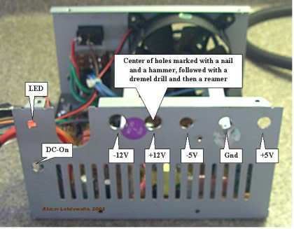
Now I drilled my holes in the cover cause I had more room in that particular area of my PSU, however what I did do was unscrew the Fan and move it to the outside of the PSU case and bolted it on. This gave me heaps more room inside.
I also took out the grommet where the thin cables passed to the outside of the PSU and luckily my switch fitted perfectly in its hole.
STEP FOUR
Next you need to attach your binding posts (sockets) to screw them in to where you've made the holes. Now at this point its up to you to either have 5 or 6 outputs, I decided to go for 5 but soon regretted it as 6 would have been better. The optional one is the ORANGE cable at 3.3v which is perfect voltage for ICs. Well anyway the choice is yours to make, suppose depends on what you want it for and how much room you have.
So once they are screwed in tightly you need to start soldering your cables to the posts. Now this is where I ran into some rather annoying issues. I neglected to think about how thick the red/black/yellow cables were and that not all of them where going to safely stay connected. So I decided to just attach a single cable to each of the posts and just run the cables (red/black/yellow) into their own connector block. This made for a much safer connection to the socket (binding post) and gave me the freedom to easily attach all my cables.

STEP FIVE
We need to hook up our resistor now. A lot of people wonder why a resistor is used, well simply a PSU needs to have a constant load across the +5v and 0v rails for it to power on and stay on. The resistor does this nicely, however it does waste a lot of power just doing a pointless job. Some people prefer to use a filament lamp or other such device to keep the load constant.
In our case you need to connect one RED wire to the resistor and the other end to a BLACK wire. Make sure you heat shrink the wires and then attack the resistor to one of the heat-sinks or the case wall. This baby will get hot so we want to be able to vent the heat quickly.
Now connect a resistor to each of your LEDs, next attach a black wire to each of the LEDs. For the PSU Power on connect the PURPLE cable to the LED (I used a red one to indicate this) and then for the DC power on connect the gray wire to the other LED (I used Green for this one)

STEP SIX
Next comes the power switch, this is optional by the way, if you don't wish to have the secondary power switch just connect the GREEN cable to a BLACK cable and heat shrink them.
If not connect the ground to your centre post and the green to the outer post and hey presto one switch.
Most ATX supplies have whats called a SENSE cable, this is usually brown in colour or Orange. If it is Orange you will know cause it's a thin cable.
Anyway you need to bundle all the orange cables and the sense cable together at this point. The SENSE cable must have a constant 3.3v for the unit to be on.
STEP SEVEN
Check your work!
Make sure you gently tug at each connection to make sure it is secure, double check your soldering.
Once done drop a bit of super glue on the LEDs to hold them in place.
Once done replace the cover, plug in a power cord. Now at this point try not to though the case in case something has gone wrong and the case is live. This shouldn't be a problem as long as it is well earthed. But for caution I would highly recommend it. Now turn on the PSU switch (by the fan) and the RED LED should come on.
At this point I went all over the box with my multimeter to ensure it was not live.
Now turn on your switch (if installed) and the GREEN LED should light up. If not you have some issues and need to retrace your steps to find out what has gone wrong. Remember to discharge those Capacitors first!
If there are not any issues then you should be able to test each socket to find out their voltages.
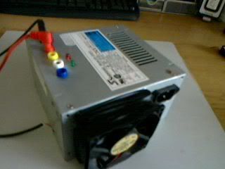
CONCLUSION
Well if you have followed the instructions here you should now know that you new Lab Power Supply works. Below I have listed some tips and also some other links from where I got some pics and the original plans I followed to build this unit.
Good luck! And remember BE SAFE!
TIPS (Taken from the WikiHow by Abizar Lakdawalla)
- Options: You don't need an additional switch, just connect the green and a black wire together. The PSU will be controlled by the rear switch, if there is one. You also don't need an LED, just ignore the gray wire. Cut it short and insulate it from the rest.
- Some newer power supplies will have "voltage sense" wires that need to be connected to the actual voltage wires for proper operation. In the main power bundle (the one with 20 wires), you should have four red wires and three orange wires. If you only have two orange wires, you should also have a brown wire which must be connected with the orange. If you only have three red wires, another wire (sometimes pink) must be connected to them.
- If the power supply does not work, that is, no LED light, check to see if the fan has come on. If the fan in the power supply is on, then the LED may have been wired wrong (the positive and negative leads of the LED may have been switched). Open the power supply case and flip the purple or gray wires on the LED around (make sure that you do not bypass the LED resistor).
- If you are not sure of the power supply, test it in the computer before you harvest. Does the computer power on? Does the PSU fan come on? You can place your voltmeter leads into an extra plug (for disk drives). It should read close to 5V (between red and black wires). A supply that you have pulled may look dead because it does not have a load on its outputs and the enable output may not be grounded (green wire).
- ATX power supplies are "switch-mode supplies"; they must always have some load to operate properly. The power resistor is there to "waste" energy, which will give off heat; therefore it should be mounted on the metal wall for proper cooling. If you will always have something connected to the supply when it is on, you may leave out the power resistor.
- Feel free to add some pizazz to the dull gray box.
- You can also convert this to a variable power supply - but that is another article (hint: Uses a 317 IC with power transistor).
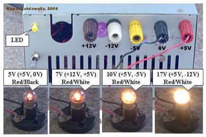
- The voltages that can be output by this unit are 24v (+12, -12), 17v (+5, -12), 12v (+12, 0), 10v (+5, -5), 7v (+12, +5), 5v (+5, 0) which should be sufficient for most electrical testing. Many ATX power supplies with a 24-pin connector for motherboards will not supply the -5V lead. Look for ATX power supplies with a 20-pin connector, a 20+4-pin connector, or an AT power supply if you need -5V.
- You can add a 3.3 volt output to the supply by hooking the orange wires to a post (making sure the brown wire remains connected to the orange bundle) but beware that they share the same power output as the 5 volt, and thus you must not exceed the total power output of these two outputs.
- To get more room you can mount the fan on the outside of the PSU case
- If you don't feel like soldering nine wires together to a binding post (as is the case with the ground wires) you can snip them at the PCB. 1-3 wires should be fine. This includes cutting any wires that you don't ever plan on using.
- The +5VSB line is +5V standby. This provides up to 1A of current, even when the main DC out is "off". It might be useful to drive an LED from this as an indication that the mains is on.
LINKS
- http://www.wikihow.com/Convert-a-Computer-ATX-Power-Supply-to-a-Lab-Power-Supply
- http://web2.murraystate.edu/andy.batts/ps/powersupply.htm
- http://www.wikihow.com/Add-Variable-Voltage-to-Your-Atx-Based-Bench-Power-Supply
- http://www.wikihow.com/Use-an-Old-ATX-Power-Supply-As-a-Lab-Power-Supply-Without-Modification

No comments:
Post a Comment